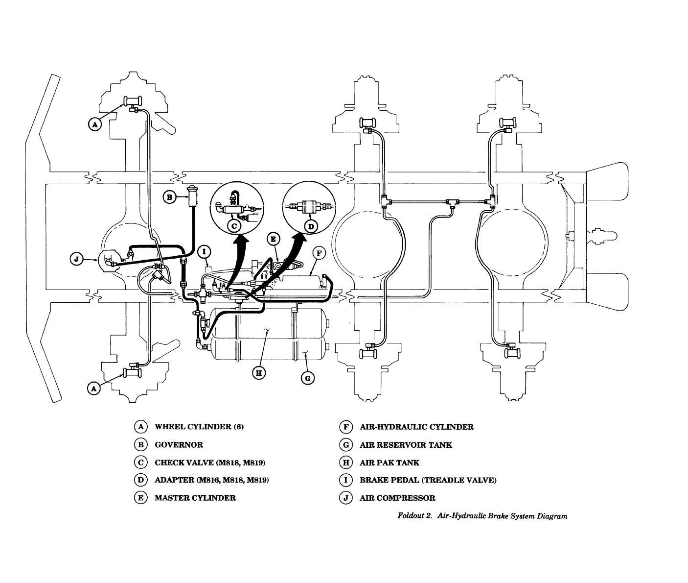
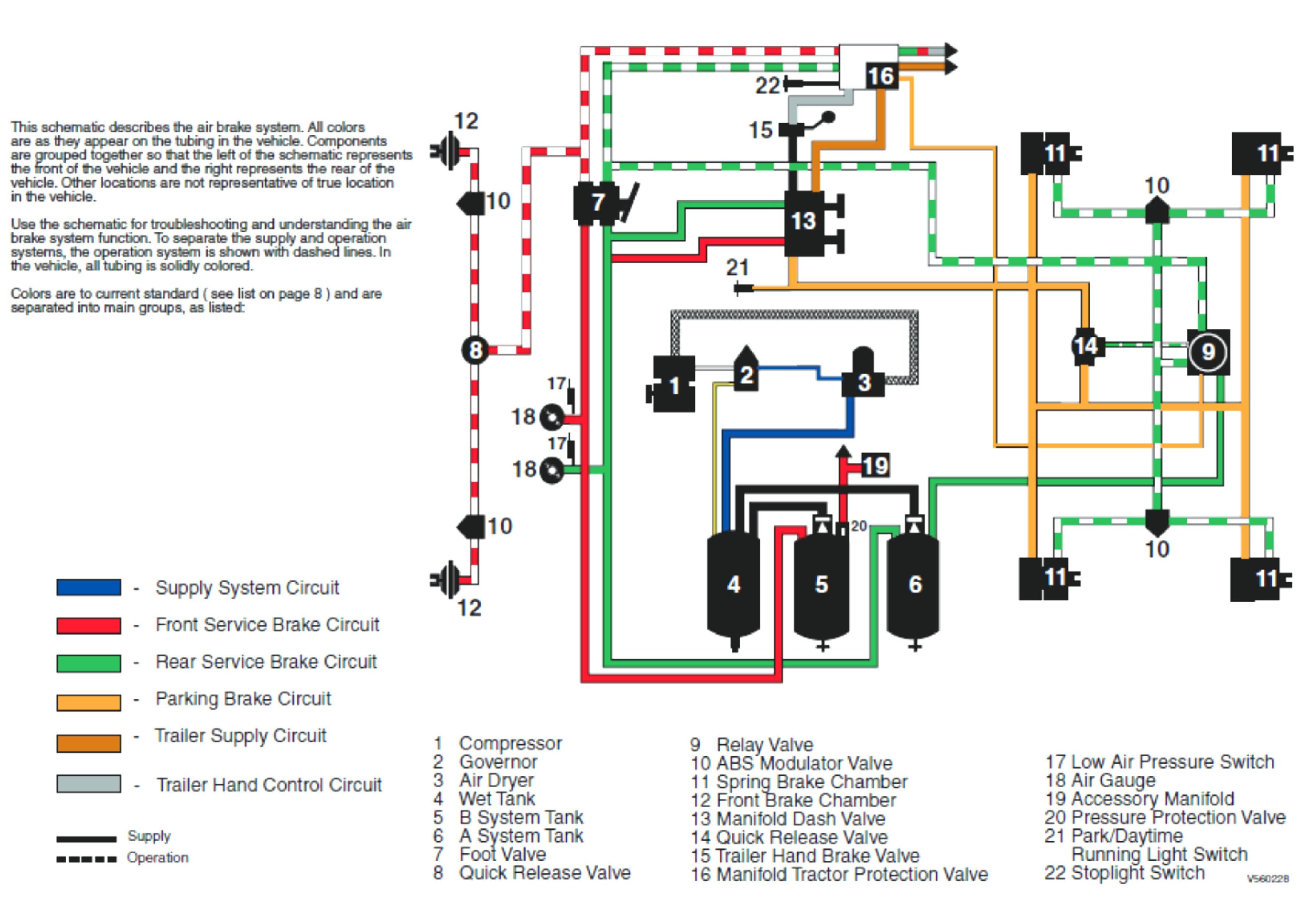
[DIAGRAM] Truck Air Brake System Diagram Manual
How does an air brake system work? Brian Murphy, Universal Technical Institute (UTI) Education & Development Program Manager, Curriculum, helps answer how do air brakes work, which is covered in the UTI Diesel program. How Truck Air Brakes Work Air brakes on trucks work using compressed air instead of hydraulic fluid.
Air Brake System Principle and Working mech4study
An air brake or, more formally, a compressed-air-brake system, is a type of friction brake for vehicles in which compressed air pressing on a piston is used to both release the parking/emergency brakes in order to move the vehicle, and also to apply pressure to the brake pads or brake shoes to slow and stop the vehicle.
Peterbilt Air Brake Diagram My Wiring DIagram
By Mark Quasius, F333630 August 2016 Hydraulic brakes perform well on relatively lightweight motorhomes, but heavy vehicles need more braking capacity. That's why diesel-powered Type A motorhomes usually are equipped with air brakes. Read on to gain a better understanding of air brake systems.
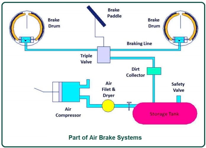
What Is Air Brake Systems? Working of Air Brake Systems Part of Air
Diagram 1-1. Air brakes differ from hydraulic brakes. Most brakes are located at the wheels of a vehicle. The force you apply to the brake pedal is transmitted to the wheels to make the brakes operate. There are two main ways in which this force is transmitted - hydraulic brake systems and air brake systems..

Tractor Trailer Air Brake Schematic
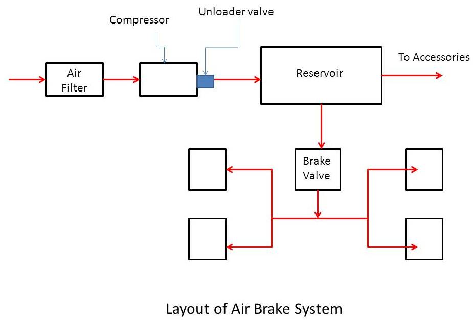
Air brake systems are made up of several subsystems. This chapter explains the operation and function of the air-supply subsystem, which produces, stores and manages the compressed air used by the brake system. Note: There is a circuit diagram of the air-supply subsystem here. Air compressor. An air compressor produces air for the brake system.
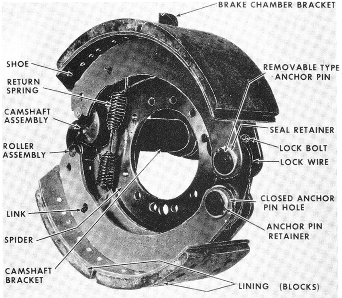
Air Brake Basics Military Trader/Vehicles
Air pressure is then required to release the parking brake and set the vehicle in motion. In case of service brakes which are used for regular operation of the vehicle, a pedal is pushed for stopping or engaging and disengaging the brake. air braking system working. Generally, a pressure of 6.8 to 8.2 bars is used for this kind of application.
freightliner air brakes My Wiring DIagram
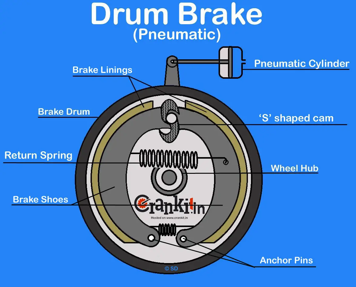
Air Braking System Diagram : Working principle: Difference between air brakes and hydraulic brakes : Probable causes and remedies of the air brake system Advantages of Air Braking System : Disadvantage Of Air Braking System : Applications of Air Braking System: Construction and working of Pneumatic ( Air) Brake System used in Automobile

box truck air brake diagram
This video gives an introduction and brief look at air braking systems on heavy and commercial vehicles.You'll see from the animations that all systems have.
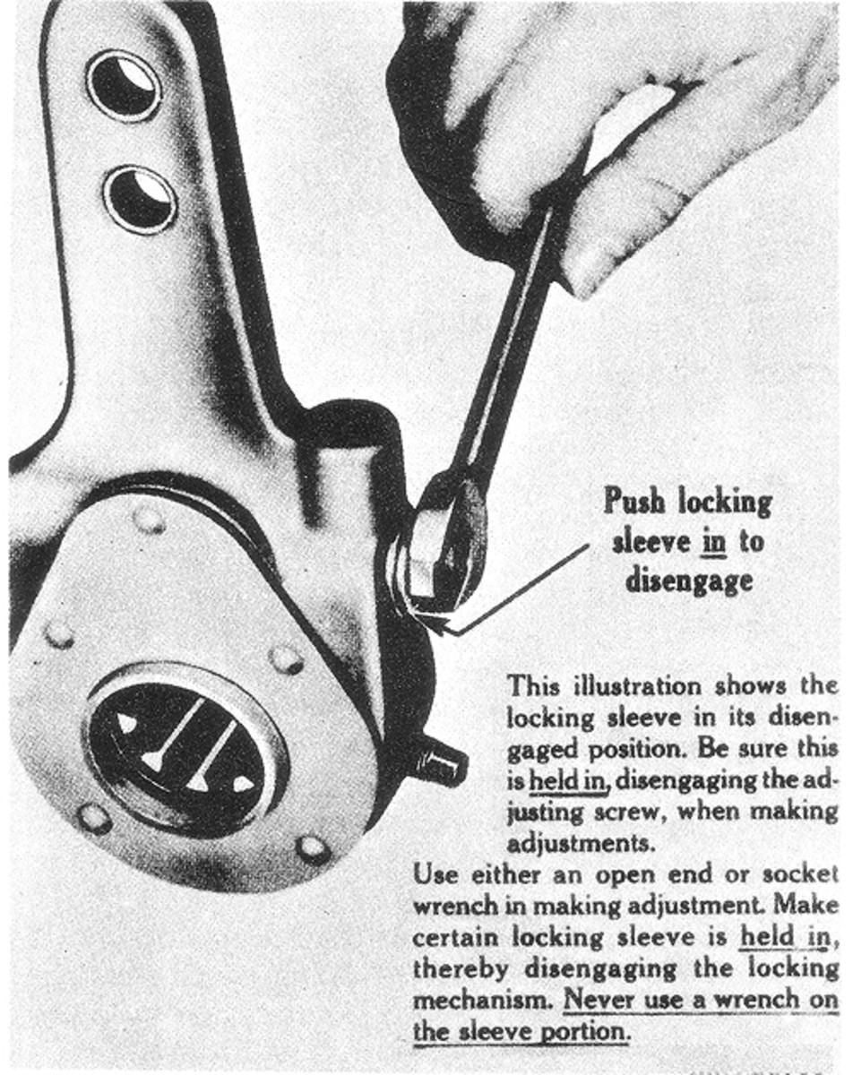
Air Brake Basics Military Trader/Vehicles
Brake Pedal. You apply the brakes by pushing down the brake pedal (also called the "foot valve" or "treadle valve"). Pushing the pedal down harder applies more air pressure. Letting up on the brake pedal reduces the air pressure and releases the brakes. Releasing the brakes lets some compressed air go out of the system, so the air.
How Air Brakes Work Diagram
Brake actuator Triple valve Air filter or dryer Parts of Air Brake System #1 Air Compressor The air compressor helps to suck atmospheric air into the storage tank or reservoir. It compresses the air to the desired pressure and transfers it to the storage tank. An air compressor is driven by the engine using a belt drive.

Air Brakes Diagram Air Horns by Grover Products
11K 1.2M views 7 years ago Educational Mechanics A more detailed look at the air braking system, in particular with this video at the air brake relay. Relays are fitted to an air braking.
How Do Air Brakes Work Diagram Photos
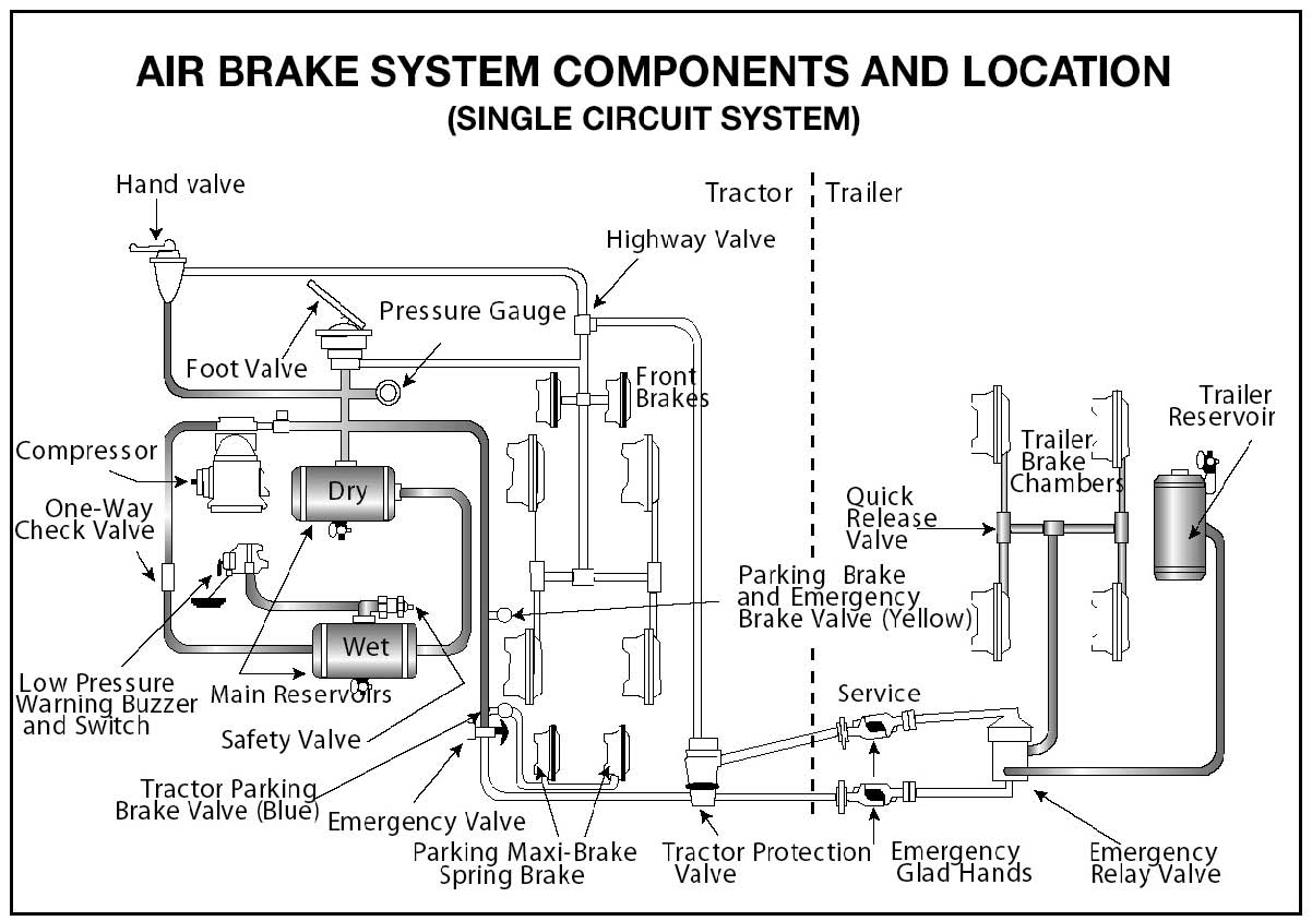
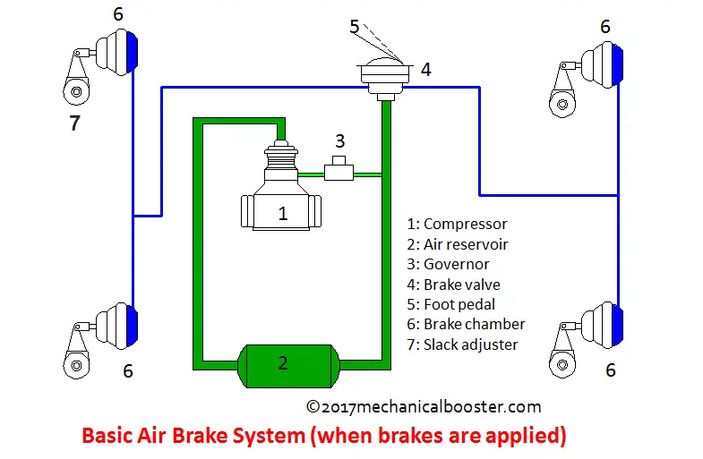
= Air Brake System Parts = Dual Air Brake Systems = Inspecting Air Brakes = Using Air Brakes There are many parts to an air brake system. You should know about the parts discussed here. The air compressor pumps air into the air storage tanks (reservoirs). The air compressor is connected to the engine through gears or a v-belt.
A Dual Air Brake System Is Best Described as
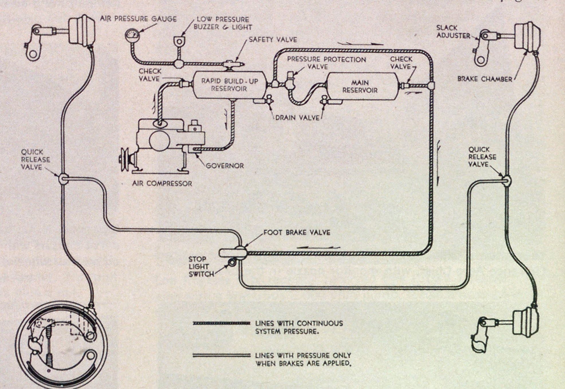
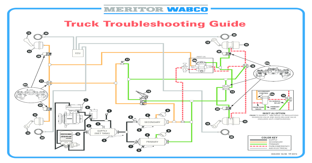
The diagram provides a visual representation of how the air flows through the system, highlighting the key components such as the valves, chambers, and hoses. The Wabco air brake system diagram also highlights the role of the brake pedal and the control valves in regulating the airflow and applying the brakes.

Bendix Air Brake Schematic
There are two types: Manually operated by turning a quarter turn or by pulling a cable. You must drain the tanks yourself at the end of each day of driving. See Figure 5.1. Automatic-the water and oil are automatically expelled. These tanks may be equipped for manual draining as well. Automatic air tanks are available with electric heating devices.
Air Brake System Diagram [PDF Document]
Overview Test Series An air brake system is a mechanism that utilises compressed air to facilitate efficient deceleration and stopping of vehicles by applying pressure to brake components. This system stands as a pinnacle of safety and efficiency in various vehicles, ranging from automobiles to heavy-duty trucks and trains.
truck air brake diagram
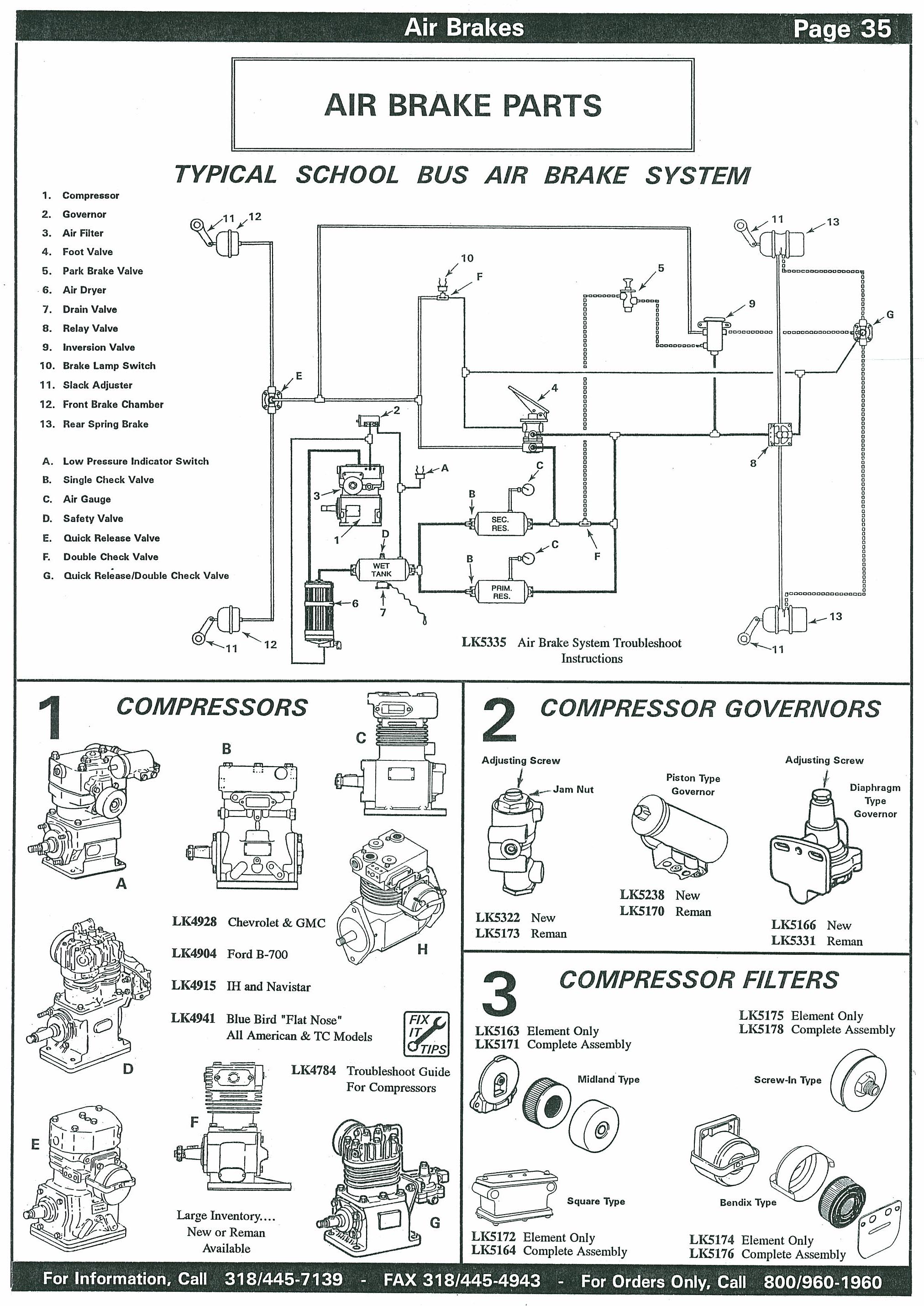
air brake systems and devices. Components are introduced and shown with typical system diagrams to show where they are used. As new components are introduced and their function explained, they gradually build up to a complete functioning air brake system. Partial systemdrawings, throughout the manual, assist in explaining of the use of the.